Re-configuring USB cables for connection to the 6 port USB 2.0 PCI card
The 6 port USB PCI card featured on our website includes 3 internal USB pin headers (10 pin
5 pin and 4 pin).
The 10 pin header supports two USB devices (one for each 5 pin row).
The 4 and 5 pin headers each support a single
usb device.
The 10 and 5 pin headers use a slightly unusual layout for the connections in the header.
Before connecting any device to the these headers you will need to adjust the order of the wires in
the connector on your USB cable so that they match the order used by the card.
If you are not familiar with the way USB pin headers are used you can find more
information in the USB cables help section.
USB cable help
Adjusting your USB cable connectors
The wires in your USB cable should be colour coded, red, white green and black.
Note if your cables use different colours you will need to make sure you know which wires
are used for each of the USB functions shown in the table below.
The picture below shows how the red, white, green and black wires should be connected to the pin headers on
the USB card.
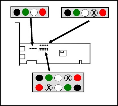
The colour coding for the pins corresponds to the following USB functions.
|
Red
|
V, +5v
|
|
White
|
Data-, D-
|
|
Greeen
|
Data+,D+
|
|
Black
|
G,GND or Ground
|
|
X
|
Not connected
|
To modify your cable for connection to the USB PCI card headers,
you simply need to remove the pins from the connector and replace them in the
correct position.
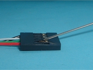
To remove the pins simply raise the small retaining tab on the connector by a small
amount using a pin or some other small object as shown in the image below.
Once the pins have been removed they can be slotted back into the connector in the
position.
For the 10 pin header, your device should have 2 separate cables. Connect one cable to
each row of the pin header.
If your cables have an extra black wire this can be connected to the pins marked X on the
picture.
For the 4 pin header this extra wire can be left disconnected.